
Created by Phil Eveleigh
Part 1
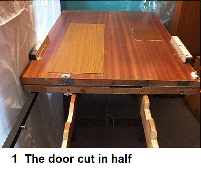
I had laying around a spare door which had been cut in half. I had looked at this several times thinking what can I do with it. Having seen the several layouts on doors in the N Gauge Society Journal it struck me that I could build a layout on it, it would also be easy to transport in the car.
I could use it to try out ideas and new techniques and it would give me somewhere to run engines in, I could also bring it to the Exeter meetings for running.
The first problem was how to bring the two halves back together.
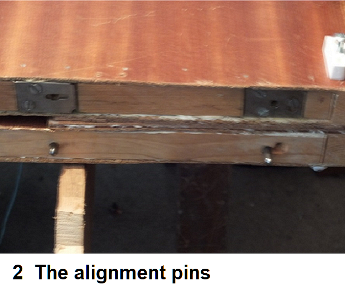
Take two pieces off timber that are slightly wider than the thickness of the door and plane them down so that they are a good fit between the ply of the door surface. Clamp them together making sure they are level, When happy drill holes through one piece and far enough into the other for dowels to be inserted. I made it an interference fit. I used metal dowels but wooden ones will do. Now split your two pieces off timber and put some glue on your dowels and hammer them home in the blind holes (I used three but two would be fine). Now clamp steel plates over your open holes and drill them out to the same size, remove them and drill holes in plates out to give a slight clearance. You now need to mark out the position of your plates and rebate the timber so that the plates fit flush with the timber (see photo’s 1 and 2). Now remove sufficient cardboard infill from both halves off the door so that your timber will insert fully and flush with door edge. Now add your prefered glue to one timber section and using the other piece to hold onto, insert it between the ply, then pin with panel pins so the ply is tight to your timber. Now repeat for the other half but this time you will have to push the other door half over the timber. You now have a complete door which can be split for storage or transport.
Part 2
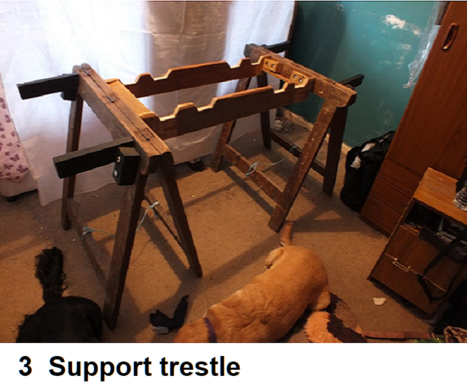
Having got the two halves of the door to fit together as one I now needed a way to keep them tightly together so that trains could run across the joint. The frame work to sit my door on is made from “A” frame trestles as I had these to hand but you could use a more conventional base.
My first answer was to use the jointing blocks sold to joint tops to the sides on furniture (see photo 1), you can see one fitted on the left hand side, one half off the block being on the top door and the other on the lower. I did also have one on the right side but this later failed and so I removed it. The frame work you can see below the door had not been made at this time and so the two halves tended to flex until the next part was added which meant that the block moved. I shall cover the building of the frame in part 3.
I next cut some timber I had into four pieces each about 8 inches long. I then drilled three holes through each piece. I drilled these over to one side about a quarter distance in, this was to allow for the timber frame down the side of the door which you need to screw into( you can see the side frames in photo 1 ), they need to be large enough to allow the wood screws you are going to use to pass through. I then glued and screwed them to the door 6inches in from the joint ends (see photo 3).
I next joined the two door halves together on there back and took two pieces of timber long enough to span between the blocks fitted above (see photo 4 ) and clamped them to the inside of the blocks with G clamps ( if you put pieces of scrap timber between the clamp and your working timber you won’t mark your work ) and drilled through both pieces of timber in two places on each block. I f you drill these 2 inches in from the end of the blocks it will make life easier later on. I drilled mine haphazard and so they are not all the same which means the stays for my covers will not run square. I had not thought about covers at this stage. You will see later why you need them the same. I drilled my holes 8.5mm to suit my bolts. When you have drilled all eight holes remove the clamps and open out the inner side of the holes in the blocks to take T Nuts and then with the help of a G clamp squeeze the nuts home (see photo 3 and 4). Now bolt your jointing pieces to the blocks to give you a good tight fit (photo’s 5 and 6).
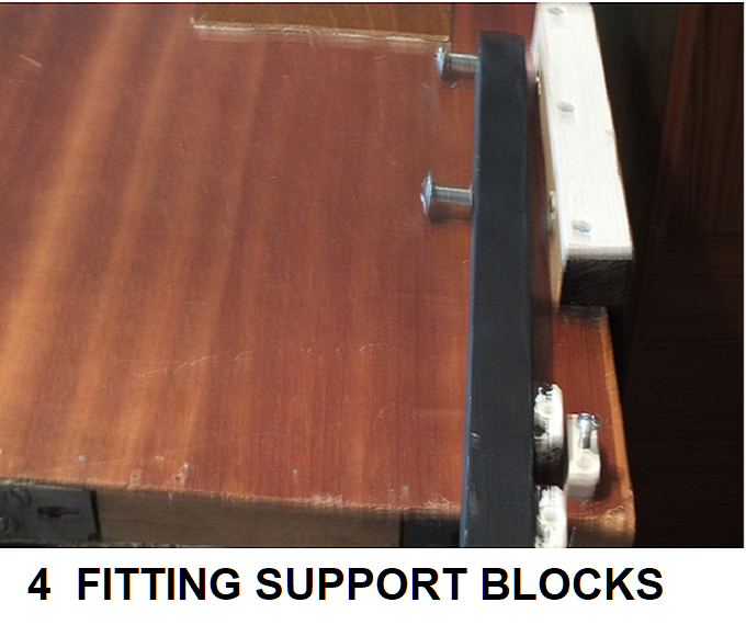

Looking at the photos you will see that I have used screw headed type bolts. This was because my holes ran to tight to my door to be able to get a socket on to the bolt heads. Had I stayed with bolts I would have had to use an open end spanner to tighten and release them which would off been long winded. Your fit is now strong enough to allow you to move the door as one if you wish.
I now started to think about laying track, which because of later thinking was a bit early. I had decided that I wanted to keep all wiring on top and so I layed 1/8 cork on the areas where I was going to lay track. This was for two reasons (1) to help deaden sound and (2) so I could bury cable etc. in the cork. You can see the cork which is stuck down with No More Nails in photo 1 sandwiched between the two door halves. The reason for having all wiring on top was so I would not be in danger of snagging underneath, also I thought that to drill holes through the door and then feed wires through without the wire taking a route of its own some where in the of the door was very remote. For similar reasons I started to think how am I going to protect the track and scenery. So I started thinking about covers. To begin with I was thinking about a complete cover for each door half and then it dawned on me if I clamp the two door halves together with stays then I shall save on timber and height ( the later being important in the car and for storage at home). I mulled things over in my head for some time and did several sketches of ideas before coming up with this solution, though at this time still half baked.
The four blocks each had two T nuts and holes. If I ran bolts through from the other side so that they entered the nuts from the rear I could bolt the stays on using these. I tried a bolt and it worked fine. My blocks over lapped the side of the door so if I nailed ply wood to the inside of the stays it would sit in the gap made by the stay. My first thoughts were that the four stays would be fine but then on a closer look at the door I saw that all the weight would be supported at one end only, so I made up four more blocks from the same timber as the earlier blocks but this time four inches long.
Again drill screw holes a third of the way across the width (you only need two in each block) and then turn the blocks on their side and mark in 2 inches, drill a 6.5mm hole in each block at this point and then open out to take a T nut. You do not need a 8mm bolt for this as a 6mm will take the weight (see above how to fit T nuts). Now screw your blocks onto the underside of the door 6inches in (same distance as earlier blocks) from the other end of the door. I now made up four short stays to hold the two door halves apart. I made short ones as at the moment I do not know what clearance I shall need to clear the scenery. (See Photos 7 & 8)
When I screwed the stays on so that the two door halves are back to back and picked up the whole assembly the bolts and T nuts which were on the outside of the short blocks pulled out. I then glued the T nuts in place and left them for 24 hours before trying again. Once again they pulled out. I did not have 6mm bolts long enough to pass through the blocks, but had spare 8mm bolts which were long enough so I drilled the holes out to 8.5mm and bolted it all together again fitting ordinary nuts on the bolts. This worked fine. You could drill the hole straight through at 6.5mm and fit the T nuts on the inner face. When you then screw through from the outside and take the weight the T nuts will be pulled tighter.
Part 3
Its now time to sort out your base to stand your layout on. As I said in part 2, I had two ‘A’ frame trestles which I could use. You may go for a conventional stand but below are the problems encountered and my solutions. Hopefully you will find something of use.
Balancing my two halfs of the door over the ‘A’ frames while trying to join them I found it hard to keep the two halves on the ‘A’ frames. I first made some brackets to take the weight at the outer ends. To make these I made up four blocks and drilled two holes through them so that I could bolt them to my ‘A’ frames (I used 8mm bolts again but 6mm would do). Put your door together as decribed in part 2 and lay your door over the ‘A’ frames, then take each block in turn and bring it up under the door and clamp it with a ‘G’ clamp to the outside of the ‘A’ frame. Once you have all four blocks clamped on remove the door and drill the holes through the ‘A’ frame. Now bolt the blocks in place. I had to counter bore my blocks as I could not find bolts long enough to pass through the blocks and the ‘A’ frame. My blocks are 4 inches long with the holes drilled one inch in from each end. See photo 9. I then cut some timber about 8 inches long and put the door back over the ‘A’ frames. Using a combination squire I set the angle between the door and the treasle. I then marked this on one off my pieces of timber and cut the angle. Now bring your piece of timber up under the the door and against the treasle and the block and clamp it in place. Repeat this for the other three pieces of timber. Then remove the door and drill screw holes through the timber so that you can screw them to the blocks. Putting the door back on and then splitting it I found that the two halves sat back fine but when you pulled them forward to join them they could fall down in the middle.
At some point while the door is on mark its .possition in relation to your ‘A’ frames so that you know you have the door balanced. I later painted the lines white so I could see them with ease when looking from below.
To overcome this I made up a frame to fill the gap. I had a block that was the right length (my piece was 11.5 inches long but a foot or 30 cm would be better) but did not have a second piece long enough. I did have a piece that was a lot shorter but if cut in halve would be usable as two blocks. I drilled two holes in each block and clamped them to my ‘A’ frames so that they were all equal and then I drilled the holes through the ‘A’ frames and bolted them in place ( again I used 8mm bolts). (See photo’s 4 & 9 above in Part 2). One of my small blocks twisted a bit which I had not noticed at the time so watch that the same does not happen to you. I had drilled the holes before I spotted it. With the ‘A’ frames in the right position I measured the distance between the tops of the frames and found some timber that was that length or longer and marked my measurement on to them. Then with the door back in its proper place on the ‘A’ frames and using the combination square again I set the angle between the door and the frame. Transfer this to your timber and mark it off so you can now cut the angles at each end. Now place your timber in place and mark round your block and then drill your screw holes in the area of the block in your timber, bring it back to the block and screw in place. Repeat for the other side. My timber was three quarters of an inch thick. On the end where I had used two blocks I later screwed a tie piece off timber between them as I found when I came to fit the frame I had to adjust its position due to flex. ( Again see photo 9 and please forgive my dogs who got in on the act ).
When I came to unscrew the screws holding my jointing pieces joining each half of door I could not get the screwdriver square onto the screw as my frame blocked the way so after marking the positions I cut out the area to allow my screwdriver to pass through (see photo 9 ). If you have used 6mm screws or bolts you may not need to do this as you will be able to use a shorter/smaller screwdriver or socket and ratchet.
Part 4
As I said in part 2, I stuck 1/8th inch cork to the door where the track was being laid. I first laid cork to the front half of the door which was going to be the scenic part. I then laid out track at the back to get an idea of the area required for the fiddle yard and then marked with a red pen the depth so I could cut cork to cover the area which again was stuck down with No More Nails, I left a bit at the ends for the curved track to be worked out later. I now took a straight length of code 55 Peco track and laid it onto the cork along the back edge and then curved a second length around so that it would come round to the front but far enough in from the front for my heritage station to fit beyond it. I wished to have the heritage station in the front with a modern station behind it and each run independent from the other but to allow through running there would be a link between the two at both the station and the fiddle-yard ends. I wished to have the fiddle yard connection on the left hand end when standing at the back looking forward but trials showed that it was going to be tight to fit in without the turnout being on the curve. The answer was to use a curved turnout so that my curved track would flow into the turnout thus easing the transition. I purchased a curved turnout and connected it to a straight medium insulfrog turnout which was in turn connected to a straight length of track which was all laid along the bottom edge, now bringing my curved track back in I could see that it would work well. I then removed the curved track and marked around the other track with a red pen and removed the track. Now I stuck down some Woodland Scenics trackbed (you can either use No More Nails again or PVA glue. I have used both across the layout with equal success) in the area marked out in red. At the joint between the two door halves leave a gap for some screws. See photo 10. I used insulfrog simply because I had some going spare and I felt that should a train stall I could give a helping hand with ease as I would be on the spot, plus in the hidden area.
pic 10,11 and 12
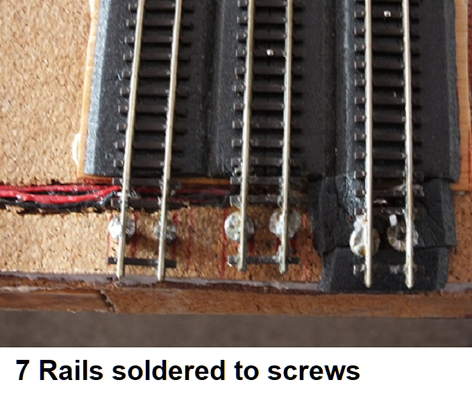
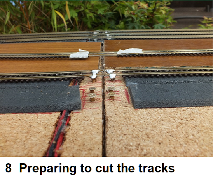
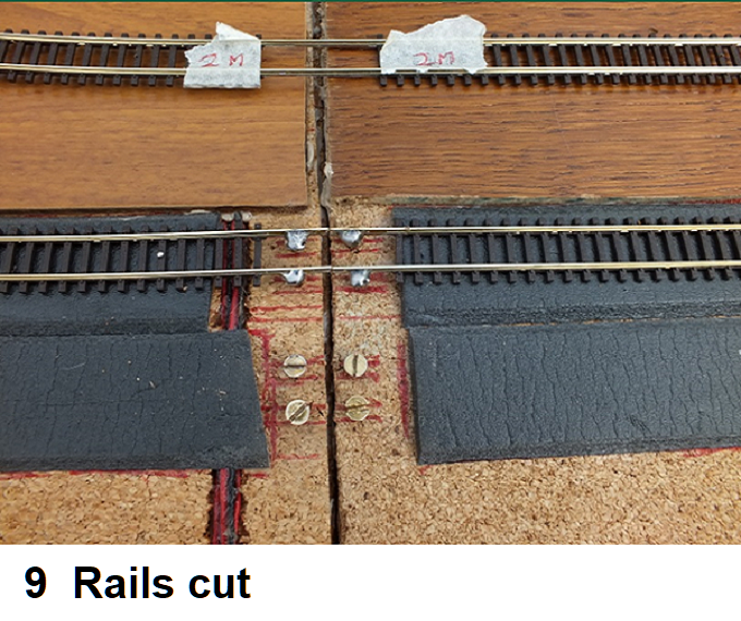
I now returned my track and marked the sleepers that would need removing with a piece of masking tape on both sides off the door joint. I lifted the track, removed the marked sleepers and replaced the track, taking a red pen and marked along the sides of the rails onto the cork so that I could see where the screws would go. I now put in four brass screws each to sit under a rail on each side of the joint and returning the track adjusted the screws so that they just touched the underside of the track. You will have to move the track on and off several times until you get the adjustment right so that the track sits level and the screws are just touching. Once happy tin the underside of the rails in the clear area and the tops of the screws. The track on the right hand side of the joint will need a power feed. I removed the last sleeper and soldered feed wires to the underside of the track ends. I now opened up the holes in the sleepers for track pins and laid the track back in sticking it down with PVA glue, once happy with the tracks position solder the track to the screws and after allowing a short time for the solder to set cut through the rails at the joint.
Now moving to the first turnout. This is for entry to the modern fiddle yard. As said above I used a Peco insulfrog medium left radius turnout as I had some to hand. So as not to rely totally on the blade contact for electrical continuity I linked the two blades by soldering a short length of wire between the blades, cut the plastic away between sleepers, see photo 13.
pics 13,14 and 15
Again I opened the holes for the track pins and as other tracks were going to be laid beside this one which meant that a turnout motor could not be mounted straight on to the side off the turnout I took a length of 1.25mm diameter rod and a 2.50mm diameter tube, turn one end of the rod up through 90 degrees (ie at right angle) and slide the rod through the tube, now insert the turned up end of your rod through the hole in your tie bar on the turnout. It should go through but if tight relieve the hole with a small drill. In both cases do not force and support the tie-bar so as not to bend it. See photo 14 and 15 (these photo’s show a three way turnout set up). Now connect your turnout to your track and temporally pin it in place, lay the rod and tube out at a right angle to the track and mark with a red pen its position on the cork and the track bed.
Now remove the turnout and carefully cut out a channel in the cork so that your tube will sit down in the cut out, also continue the cut into the trackbed so that the rod will be buried in the trackbed. If your two wires that you soldered between the blades sits below your turnout then also cut slots so that these will sit down in the trackbed and not hold the turnout up. As the tube is the same length as the rod it will need to be shortened so that the other end can be bent up through 90 degrees. I worked out the position of the other tracks in order to find how long the tube needed to be to clear all the tracks. Once happy I applied some PVA glue to the trackbed and connected the turnout to the track and pinned it in place, laid the tube and rod into the cutout and after moving the tube out slightly so that there was sufficient movement for the rod to operate the turnout I then applied Evo-stick Serious glue along the outside of the tube in order to stick it down within the cutout, do not get any glue on the rod.
pics 16 and 18
I now took my Peco electrofrog curved turnout and cut away the plastic between sleepers so that wire could be soldered to the stock rails plus a third wire soldered to the wire under the frog. See photo’s 16, 17 and 18. These wires will go to a Peco switch so that the polarity will switch when the turnout is switched. I connected the turnout to the rear of the previous turnout and marked with the red pen the run for the wires on the trackbed. I removed the turnout and cut the trackbed so that the wire would sit down in the trackbed and not hold the turnout up and also cut out a section of cork to take the cables out to the turnout motor. I did not require a rod this time as the turnout motor will be connected to the turnout by the base plate being connected by the raised pin on the tie-bar, see photo 19.
pics 19
I soldered a pair of wires to fishplates which following cuts in the trackbed were pushed onto the rear of the turnout, these are feed wires. I now set up a Peco insulfrog right medium radius turnout as the first one and connected it to the spur rail on the earlier one so as to give me two more roads. Prior to gluing this turnout down I added two more runs of trackbed. All turnouts and track is glued with PVA glue and pinned to the track bed. I now added two more tracks with feed wires again soldered to the far end. I now cut a channel for these wires through the cork and glued it down with the Serious Glue, I also glued the tube from the second insulfrog turnout into its cutout. You will have missing sleepers at the track joints and by the screws, first insert some small pieces of trackbed into the gaps secured with PVA and then slip some spare sleepers under the track and space them to match the other sleepers, glue them in place with more PVA. This now completes the modern fiddle-yard.
I now laid my curved length of track at the opposite end and worked out the curve required. I finished with the Heritage station end set in slightly so that a track will fit on the outside. I originally wanted to have the tracks running across the front at an angle but found that to do this it would make the curve at the other end to tight so I had to settle with the tracks running parallel to the front. Once I was happy with the run I marked along the sides of the track with the red pen onto the door and removed the track and then cut sections of cork suitably shaped which were stuck down with No More Nails. I found it best to do the curve in sections. Now I cut short lengths of track bed and cut them down the middle (you will find a line down the middle of the track bed) so that I could curve it round. Each piece was stuck down with PVA glue, glue the inner piece first. You will find that the outer piece finishes up short of the inner so you will have to make this right at the end of the curve. I left this for a day to set firm before pinning and gluing the curved track in place.
pic 20, 17
I now took a Peco electrofrog 3 way turnout and soldered wires to the wires on the underside (connected to the frogs) and also two to the lead end rails (I soldered to the joiners) in order to connect to two Peco switches on top of turnout motors. see photo 20 above (NOTE If you look closely at the second purple wire you will see that this is not required as Peco have already made the connection for you. I had blindly followed the instructions, Peco must have carried out a modification on this area. I shall see later if it is needed or not but believe it is not. See later section when I wire this up to the control panel). I put a plastic tube over the wire and the wire already fitted to the turnout. This is to help insulation and also to protect the joint. I use tube found in hand soap dispensors and kitchen cleaners. Run plenty of running water through the tube to clean it out and make sure it is dry before using. I now temporally laid the turnout in place and marked the postions of the wires and also the rods for the turnout blade switching and using a straight edge carried the lines out to the edge of the cork at a right angle to the turnout. I took the lines right out in order to get behind the backscene. I now removed the turnout and cut slots in the cork to take the wires and rods. See photo 14 in part 3. Once I was happy I glued and pinned the turnout down.
This will continue in part 5 where I shall finish laying the track and start the wiring.
Part 5
I have given the layout the name of Palton. When describing what I was building to members at meetings I said like Paignton and Alton where the modern railway meets the old. So I combined the two places together to come up with Palton.
We ended part 4 at the three way turnout. I now laid a meter length of track from the outer spur again crossing the joint with the screws, as done before in the Mainline fiddle yard. This time the feed wires were soldered just after the joint as there would not be room further down and the main feed wires would be back at the start of the fiddle yard (see next paragraph). Once again a slot was cut in the cork for the wires to sit down in. Once stuck in place I laid the two other tracks in place loosely and worked out how much length I needed for a train to sit in the station without fouling the turnouts. I now laid a medium radius left hand electrofrog turnout on the top of the center track and connected a double slip electrofrog turnout to its left spur. At the moment I used metal fishplates. Once happy I marked the cut points for the tracks to connect to the turnouts with pieces of masking tape. I marked along side the tracks with a red pen and removed the track. I now laid in the trackbed for the centre track taking it on beyond the turnout. Having cut the track I laid it back on the trackbed and connected the left hand turnout so I could workout where the cutouts in the cork were required for the wires and the rod. Once this was done and the rod had been made as before, I glued and pinned the turnout in place using PVA and using the Serious Glue, stuck the wires and the rod into their slots. I now laid more track bed in for the third track, again I took it beyond the double slip. I now brought the double slip back in again using metal fish plates so that I could work out the position for slots for the wiring and the rods ( I used metal fish plates for this setting up as insulating fish plates are not so robust ). I had already wired the double slip by soldering wire to the wires already attached similar to the three way turnout. As the double slip has to be totally insulated from the rest of the track I also soldered feed wires to the outer rails. See photo’s 15 and 24 which show opposite ends of the slip. You can see the wires between the sleepers. Besides the wires you will need two rods in order to get beyond the back scene for the turnout motors.
I now returned to the fiddle yard end of the Heritage line and installed a right and a left hand insulfrog turnout (again because I had them to hand) at the end of the curve. Again I had soldered wire across between the rails see photo 13 in part 4. The right hand turnout came first and I soldered feed wires to the fish plates that connected it to the curved track (mentioned above in last paragraph) installed in part 4. I next laid in a length of track from the straight on spur on the right hand Insulfrog so that it ran beside the main line fiddle yard and then curved round to join the curved turnout laid at the start (see part 4). Once happy with the run I marked down the sides of the track with the red pen, removed the track and stuck trackbed along the course leaving a gap by the join on the door. I now laid the track in as before soldering at the door joint to the screws. I did not need feed wires after the door joint this time as the feed will come from the feed at the curved turnout (see part 4). when that is set to this track. A lot of the work will now be on the left hand half off the door when viewed from the rear, so I could now just get this half out when I wished to work on it which saved a lot of time. I am unable to leave the layout set up.
I returned to the Heritage Station end. We left it after installing the Double Slip and beyond it and the left hand turnout on the centre track I wished to have the engine shed. I loosely laid a straight length of track from each and taking two Peco engine shed ends (kit 203) and clipping (a peg) them together side by side I laid them over the tracks to see where the tracks needed to be in order to pass through the doors. From this I could see that they needed to be further apart. In order to get this right I decided to build the shell of my shed. If you join two or more of these kits you will need to do a bit of fettling. At the bottom of the buttresses you have a stepped out bit which will need removing in order for the two parts to join properly. I carefully filed this off, firstly using a courser file and finishing with a needle file. You need to do this on the right side of one and the left side of the other, you will also need to do this for the side walls at there join and the rear wall. The kit provides a thin section to bridge the join which I glued by laying two end pieces face down on a piece of glass in order to make sure they were flat and level. I then slipped the bridging piece in making sure all was in the right place and ran some plastic magic down the join. To further reinforce the join I also added a strip of plastic down the rear of the join. I treated all these joins in the same way (see Photo 25 you can see the white plastic reinforcing pieces in side) and then put the shell together again on the glass and using a squire at the corners. In the photo I have gone further and will cover this a later part.
Pic 20
I laid a length of track from the turnout on track 2 and formed a curve to the right followed by one to the left in order to come back straight again. The track from the Double Slip had been left in place. I again placed the engine shed doors over the tracks to check that I had moved over far enough. Once I was happy with the position I again marked the track position with the red pen and stuck down the trackbed to the end of the engine shed and put the track back in with the double bend. I then cut the track a little way from the second bend and then worked out how long a piece of track I required for an engine to sit insulated and then doubled this up and cut the two lengths required. To these I soldered feed wires and then laying them back in place marked the positions for the cutouts for the wires. Having done the cutouts the tracks were stuck in place with PVA glue and insulated fish plates at both joins. The wires were then stuck in place with serious glue. I now wanted a servicing pit and so took Peco’s Inspection Pit kit no. NB-56F and worked out how to fit it in place. With the kit you get two sections and I decided that I only needed one on each road as you would not be able to see a second one at the back of the shed. I took one section and laid it on top off the trackbed, it sat nicely but I needed to cut the center out from the trackbed for it to sit down flush. I marked the outer edges of the well at both ends with the red pen and then using a rule drew the lines down through. Then I cut the center out, I also had to take the cork underneath out as well for it to sit down properly. I now slid the rails into the slots in the pit and connected it to the rail already done with insulated fish plates. With the fish plates in place there was no room to solder feed wires so I added a short length of track which was connected with metal fish plates to which I could solder the feed wires.(see photo 26). I then added the last section of track with feed wires attached. I then cut the slots for these wires and stuck the pit and track in place. I then repeated all this for the other track but as the track leaving the double slip had to be insulated from it I added feed wires to this section of track as well. I laid the engine shed back in place to make sure every thing still lined up.
Pic 21 and 22
I now turned to the final road leaving the double slip. I connected a short length of track to it with more insulated fish plates and then connected a ‘Y’ turnout to it (see photo 27). This short length of track had to be curved a bit to fit in. In the photo you can see that I have a bad joint at the Y turnout. (During the summer I had this board in the garden to work on. A sudden down pour of rain came and as I needed to get electric items into the dry first the board got wet, which resulted in this piece of track moving. I shall sort this out later). Again I had the wires attached to the turnout and had made up the rod to move the blade. Again the runs for the wires and rod were marked and cut out before the turnout was fixed in place. I now took my curved piece of track that I had used at the start (see part 4) and put it back in place between this turnout and the curved one. I marked its track and then put in the track bed in the same way as at the other end. Once happy the track was glued and pinned in place. This now gave me a continuous run. From the fiddle yard, over the curved turnout onto the modern line around the curve and onto the ‘Y’ turnout, across the double slip, down track three or two of the heritage station, over the three way turnout and back to the fiddle yard.
I now had to work out my Heritage station so that I could then work out the position for the Main line station. I had bought Kestrels Town station (kit no GMKD 1000) for the Heritage station. I made up the buildings (you get a Station Masters House, Waiting Rooms and Buffet room, Booking Hall and a Parcels office in this kit) as individual shells. I added extra walls and a upper level floor to the Station Masters House. With the Waiting Rooms and Buffet building I added two cross walls in order to help keep the outer walls straight as they tended to bow due to there length. These extra walls also split the building into three rooms which matched up with the doors. With the Booking Hall I added two walls down one side in order to make the booking office. There are two windows close together down one side and I built the office around these. The Parcels Office was assembled as it is. I did not add the roofs at this stage. I now put the two halves off the door together laid the buildings roughly in place beside track 3 so I could see how deep they would go. I now took some lengths off Graham Farish platform sections which I had plenty off and clipped them together and laid them down beside track three over a long enough distance to be able to take the length of the station. I now added more on the outside of these so that my station would sit on them and give a small platform to the rear of the station as a walkway. I placed more beyond the station so that I had a gap between the two as a road and laid the sections out to make the first platform for the Main Line station. I marked the far side of this platform with the red pen. This gave me a position for the first track for the Main Line station. I now moved the platform pieces across to track three off the Heritage station and added them to the other platform pieces in order to give me a length for the platform. I marked there positition with the red pen for later and removed the buildings and platform pieces.
Coming from the other spur on the ‘Y’ turnout I curved a length of track round with various curved track setters in place and worked out were I needed to get in order to have a three way turnout feeding the station,, this also involved running a track from the turnout into the station. Once happy this was marked with the pen and the trackbed was stuck down followed by the track, the three way turnout complete with wiring as before and the rods. This time I could not do the cutouts for the rods or cables as they ran at an angle across the other rods and wiring. At this time they were stuck down with some masking tape as a temporary hold until the turnout motors were in place. Now I laid and stuck down the trackbed for the first track into the Main line station keeping on the outside of the red line marked along the platform edge. Once again the tracks would cross the join in the door and so I had to work out the position for the screws and solder the track to them. I also had to add track feeds beyond the joint. Due to the curve it pushed the platform back a bit as I wanted it on the straight for ease. Once happy I repeated for the second track. I now needed to add the platform along side the second track in order to be able to add track three as this would go down the other side. The two tracks curved into the station from the threeway turnout and so I started with the ramp then adding straight pieces worked out the run and where to cut one section for the joint. As these platform pieces clip together I did not want to have to do this at the joint each time I put the layout up and so by cutting one platform section I could stick one part each side the joint. So I put the longest carriage I was to run on the track and by running it up and down I could stick the platform sections on using the Serious Glue which was run along the bottom edge of each piece. Before the glue set I made sure I was happy with the position. My longest train will be a 159 three car DMU so I made the platform long enough to take this. This station is a terminus and so a platform edge is needed to run across the end of these two tracks. I now laid in the third track which was a bit more of a fiddle as I had to adjust it so that my carriage would run nicely down the side of the platform. This now completed all the track laying for the station.
Now for the wiring. Taking what I know as a Chocolate Block (the Nylon strips which allow you to connect two wires together using screws on the top. (They usually come as a block of 12) I stuck them down at a suitable position behind my backscene. Each block was cut down to the number required for the track feeds and returns at that positition. The engine shed area needed the full 12 secments. On the longer ones I screwed and glued them down with two or three screws. Once the glue had had time to set, I connected each wire to the blocks. I kept each tracks wires together ( red black, red black and so on). At this stage I only did the track feeds. The turnouts will be done later. Also the track wiring will be continued in part six.
IMPROVEMENT FOR JOINING DOOR HALVES
Each time I put the layout up I became more and more frustrated by the struggle to screw the screws though the jointing stays and into the ‘T ‘nuts from underneath the layout. They sometimes cross-threaded. The answer was looking me in the face. If I put the screws through from the outside I could screw them through the ‘T’ nuts and into the jointing stays. The only thing was the stays did not stay tight to the blocks, so my answer was to buy a pack of 100mm long bolts from B&Q. The pack also came with nuts and washers. Start by screwing your bolts through the ‘T’ Nuts so that they come flush with the edge of your ‘T’ Nuts (you will be able to do this by hand) and then hold your jointing stays up tightly against the side of the blocks. Now screw the outer bolts through until they protrude out the back (you will most likely need a ratchet for this) and put a washer and nut on the back. Now repeat for the inner ones. Now hold the bolt heads and tighten the nuts to pull your Jointing stays in tight. Slowly wind the the bolts home tightening the nuts as you go in order to keep things tight. The bolts are longer than required but you may like to do as I have (see next paragrath) in which case they are fine. I have also left the bolts at the rear long incase I add anything there later.
At the start of this part I laid the first track for the Heritage station from the outer spur of the three way turnout. This track runs close to the edge of the door and I could see this becoming a problem later on, so I decided to add a section to the front face. I had a couple of 6 foot by 6 inch lengths of MDF. I took one and loosely held it along the front. I could see that this was as required. I now needed a way to fix this and so I had a length of timber, similar to the blocks on the door which I could get four pieces out off. I cut these so that they would lay vertically against the blocks at each end on the half door. I now took one at a time and after measuring down from the top of the block on the door to the centre of the hole. I transferred this measurement to the new block from the top down. Now clamping the block in a vice on a drill stand I drilled the hole through by stepping up the drill size to eight point five mm. This ensured that the hole came through square. I then screwed (with bolt as para above) this block loosely onto the one on the door. Now repeat for the other three, measuring each time in case your holes are not all at the same measurement. Now put your jointing stay up behind and slowly wind the bolts through until tight as above (put washers under the bolt heads and the nuts to protect the wood).
When all is tight and your new blocks are level with the blocks on the door, take some thinner timber to make your support for the shelve. Mine was about 3 inches across. I cut four pieces five and a half inches long so that the edge will not show under the shelf. Taking one at a time, hold it onto the block so that one end is on the block with its edge resting against the side of the door and mark the position of the block underneath. Make sure your marks are such that it is central on the end. When happy drill some screw holes through and countersink the top side so that your screw heads will go below the timber top. When happy glue and screw into position. Repeat for the other three. Now lay your shelf onto the blocks and adjust its postion so that it is central. You will have a three inch gap at each end but do not worry about this for now. Holding the shelf tight to the door mark round the supports onto the underside of the shelf. Flip the shelf over onto its back and mark the postions of your screws which are holding the supports to the blocks, remember the screws closest to you on the supports will be marked furthest away from you on the shelf. You can now drill holes through the shelf in positions that will miss the screws put in above. I drilled four holes in order that the shelf will sit tight to the block and stand leverage if the shef is leaned on. Repeat for the other three positions. Now counter sink these holes on the top side of the shelf so that your screws will sit flush. When I started screwing the shelf to the blocks I found that some were not quite level height wise so I had to make up some packers to take up the gap (see photo 27). Once happy with the fit using a set square mark the cut line on the shelf where the two door halves join. Remove the shelf and cut through on your line. I said earlier that there was a three inch gap at each end of the shelf. In order to fill this I cut two six inch pieces of timber that measured three inches across, then taking two pieces of timber large enough to join the three by six inch pieces to the shelf. Screw and glue these to the underside of the shelf (See photo’s 29 and 30). Photo 31 shows the left hand door half. (Please note that the shelf has not been tightened in the photo). I have moved on a bit from the above and will cover this in part 6, in which I shall bring all up to date.
Pic 23,24 and 25
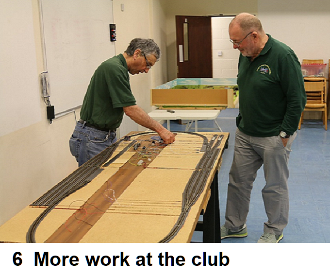
Part 6
Looking at photo 31 at the end of part 5 you can see two tracks which have not yet been mentioned. These are alongside the through track for the Heritage fiddle yard, so with the two door halves re-joined, returning to the right hand and left hand insulated turnouts installed in part 5 (in para before the engine shed). I now took a length of track and connected it to the left hand spur on the left hand turnout. Running it down the side of the through track I worked out where the sleepers needed removing in order for the rails to be soldered to the screws at the join. I also marked the run for the trackbed and installed it as before. I took the trackbed down to near the curve on the Main line but stayed far enough back so that if a train was sat at that end, the coaches on the Main line would not foul it. About half way along the track from the door join I cut the track and using insulated joiners to connect the two half’s so that I could store two trains on the track. Feed cables were attached both sides and run as at other track feeds This was then repeated for the other spur on the turnout.
I now returned to the wiring and starting at the furthest chocolate block, I ran cables down to the door join end. The feed wires were run the whole length and the return cables were run to the next block (one linking the Main Line returns and one linking the Heritage Line) I had used red wire for the feeds and black for the return to/from the track to the blocks, if I carried this on I would have a whole bunch of wires the same colour, so for this reason I used different colours for each run. The wires from each block were tied together to form a loom and the next set after tying were then tied to the loom. At the door join end the wires were soldered to a 25 way male “D” connecter. See photo 31 at end of last part. A record was made of all the wiring by drawing out the runs on sheets of paper. This is also being slowly done on the Lap Top so that I can have a printed copy made up as a book for fault finding.
CONTROL PANEL
I have several sheets of alloy and taking two pieces, I bent two inches over at a right angle on both, by clamping the sheet in a Black & Decker Workmate. The two inch part being down in the jaws. I now pushed the remainder over and finished off by tapping along the fold with a wooden mallet. If you now lift the material a short bit up in the jaws you can square it up if needed by springing it over a little more. One piece is 11 ¾” x 6 1/2” and the other 11 ¾” x 5 ½”, the one 1 inch deeper in order to rest on the 8 inch block mentioned in part two, which the stays connect too. This deeper side is to the rear and goes down the edge of the door to the block which is slightly proud of the door side. I also stuck a piece of ply under the door between the block and the end of the door ends (where the join is between door half’s). This was done so that I could put the control panel on one half to check operation on that half alone.
I next took a piece of 18”x 12” ply wood to make the mimic board. I measured in 1 inch from both edges and then drew a line down through here and worked out the positions for holes for small nuts and bolts to hold the ply onto the alloy pieces. The ply top was painted white and the mimic plan drawn out with a pencil. Having worked out where the switches had to go I drilled out holes for them, plus the holes for the studs for the Turnouts as I intended to use a probe to carry out the throw. When drilling ply, lay it onto a scrap piece of timber and drill through using increasing sized drill bits. This will stop the underside of the ply splintering. I loosely assembled it and put it on the door.
I now needed away to keep it in place. I first considered drilling through the outer face and screwing it to the door edge with wood screws, but after some thought decided that the screw holes would soon get slack with constant use and so I came up with fitting small blocks to the inner side. The timber you use needs to be deep enough to take screws through the side. I cut four blocks and with the panel in place (equal distance on both door half’s) I put two blocks on top of each other at one end of the forward side panel and drew around them and then repeated for the other side. NOTE the blocks are inside the panel. Remove and strip down keeping both sets of blocks as a set. Draw lines diagonally over one block to find the centre. Now with the sets clamped in a vice with some scrap wood beneath (in case you break through) drill through the top block and roughly three quarters into the lower. If you do this on a pillar drill you will be able to set the depth with the stop. I had two more metal dowels (needs to be shorter than the depth off the two blocks) which I measured the diameter off and so then opened up the holes to give a tight fit. I then removed the blocks and after putting some glue on the dowel, I tapped it home into the blind hole. Then putting the blocks with the hole right through in the vice, opened the holes slightly to give a clearance.
I now returned to the front sheet of alloy and measuring up one and a half blocks distance where I had marked around the blocks earlier I drew a line to give the position for screws. I now measured in half an inch from the block edge markings to mark the hole position and drilled the holes so that they were very slightly less than the screw diameter. I now reassembled the panel and put it in position and clamped it in place by using some scrap ply and timber to clamp the rear side to the door with ‘G’ clamps. I now put my two block sets in place and using No More Nails glued the lower ones in place on the door. Once set I pushed the top block down hard onto the lower block and drilled pilot holes into the edge of the top block through the pilot holes drilled above. I was now able to screw the screws home. By having left the holes in the alloy slightly tight the screws also grabbed the alloy. I now released the ‘G’ clamps and lifted the panel off. I could now put it on and off at will with it locating by the dowels. See Photo 31 in part 5 for lower block and photo 32 (with this part) for the block on the control panel.
I painted the underside and the metal sides with blackboard paint. Once dry I stuck gold coloured strips onto the top of the wood along the lines drawn earlier for the mimic board. These are the rows of strip that card makers use. You find them in craft shops amongst numbers and letters, all on backing cards from which you peel off what you require. I used gold as I had a choice of Gold or silver and I felt that gold would show up better on a white background. Once happy I painted matt varnish onto the strips in order to seal them. Once dry the double pole double throw switches where fitted. I had to leave the washers off in order to get the nut to go on. I then stuck letter ‘S’ behind the switches to mark the off position, again I used the varnish to seal them. See Photo 33. For the section of track that both the Main Line and Heritage Line share I used a larger Double Pole Double Throw switch which has six tags on, in two rows of three.
I purchased a Gaugemaster Twin Track Controller GMC-D from Hattons. They sell it at a discount though it has gone up since I purchased mine. Their prices are still less than Gaugemaster. In order to connect it to the control panel I fitted two three pin Din plug connectors and a six pin one to the rear face of the control panel, the six pin one in the middle (see photo 32 and 34). I have some cable made up with two wires inside an outer sheaf layer. I connected one set of wires to the track 1 side and a second to the track 2 terminals on the controller. I then soldered the other end to the terminals in the connectors having passed the wires down the sheaf on the three terminal connectors in the Din plugs. Prior to doing this I worked out how long I needed them to be. I now screwed and glued a four gang chocolate block to the underside of the ply wood top using short screws so that they would not break through the top. I now ran black and red wires from the rear of the track 1 and track 2 Din plugs to the chocolate block one set going to the first two gangs and the other set to the other two gangs.
I now ran a red wire from the track 1 chocolate block to the centre pin on the nearest switch for the Main Line track and taking a second piece of red wire soldered the two to the centre pin. The second wire then went to the next switch and so on, until I had run a feed around to all the Main Line switches. I then repeated this process for the Heritage Line switches but this time starting at the track 2 chocolate block (See photo 35). Now I ran wires from the female side off the ‘D’ connector which corresponded with the wires soldered to the male half (take care to get the wires correct) and ran them to the switch which controlled that section of track marked on the mimic board. Make sure you solder the wires to the correct pin on the switch. As I said earlier I stuck the letter ‘S’ behind the switches, ‘S’ for stop. So with the control panel being on its back you need to solder the wires to the rear pin. The side that the Din Plugs are. See photo 36 which also shows some leads for turnouts which go to a male ‘D’ connector. In the photo both ‘D’ connectors are connected to keep things tidy. The above process is now repeated on the other door half.
The turnouts will be covered in part 7.